Inventor® Training
Master Inventor!

Control Inventor Models with Custom Part Templates - Page 2
This is what the sketch looks like after changing the length of an extrusion by 1/4 of an inch. The bottom circle became misaligned while the top circle remained centered on the geometry.
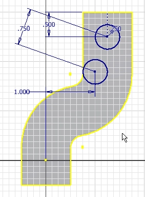
If you consider that most part changes are measured in thousandths of an inch, you can see how a problem like this might not be so easy to detect.
When part geometry changes, you want the hole location to change relative to the geometry and not relative to an arbitrarily* placed origin of a sketch. So the first step is to deactivate the setting that projects the node onto new sketches.
Follow these steps:
- Open an new part file using the Standard.ipt template.
- Click the Tools tab, and then open the Application Options.
- Click the Sketch tab, and then uncheck the “Autoproject part origin on sketch create” option. (It’s near the bottom of the dialog box.)
- Click OK.
We want the first sketch to have a node on the origin, and since you opened a new part file before changing the setting the sketch has a projected node on the origin. Now it’s time to create the template.
Create the template.
All you have to do is save the file in the Templates folder. You’ll find the Templates folder in the Inventor install folder. The path will be something like C:\Program Files\Autodesk\Inventor 2011\Templates. Save the file in the Templates folder, and give it a descriptive name. You might name it Part Fixed Point.
Once you’ve saved the file, close it.
Open a new file using your template.
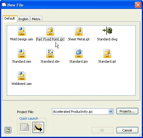
Click the New File command and your template will be in the Default tab of the New File dialog box.
Using your new template
Now that you’ve created the template you need to use the following procedure to create your parts.
- Use the projected node on the origin of the first sketch to constrain the location of the first profile(s).
- Use the Sketch Profile that’s created when you create subsequent sketches on surfaces or project geometry from existing geometry onto subsequent sketches to attain locating geometry. You’ll use the Project Geometry command in the Sketch tab to project geometry.
- Constrain profiles on subsequent sketches to the projected geometry or Sketch Profile.
It’s a simple procedure, but is give you more control over the location of sketch geometry.
Why is this important?
The template is simple to construct and easy to use, but it provides a significant benefit: the prevention of errors that can occur when you constrain profiles in secondary sketches to a node projected from the origin. As a result, you have gained more control over your models.
* Note note that sketch origins are not located in arbitrary locations. They are in line with the part origin. The term arbitrarily is used because the sketch origin is not located relative to the geometry you should use to locate sketch geometry. So the relative location of the origin is arbitrary.
Algebra the Game
Teaches Algebra while you Play!
Play on any device connected to the internet.

New!
Algebra the Course - Fundamentals
Prerequisites: None, anyone can learn.
No Installation Required
Watch from any device connected to the internet.
$19.95
Algebra the Course - Fundamentals
This course makes algebra simple. It's based on skills used in Algebra the Game, and it shows you how to solve real life problems.